
Transport
- Mechanical transport - horizontal
We guarantee a high level of quality
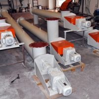
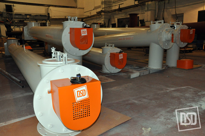
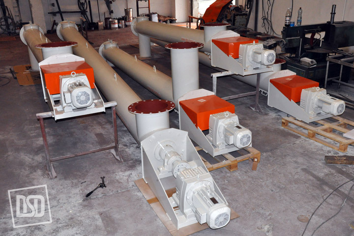
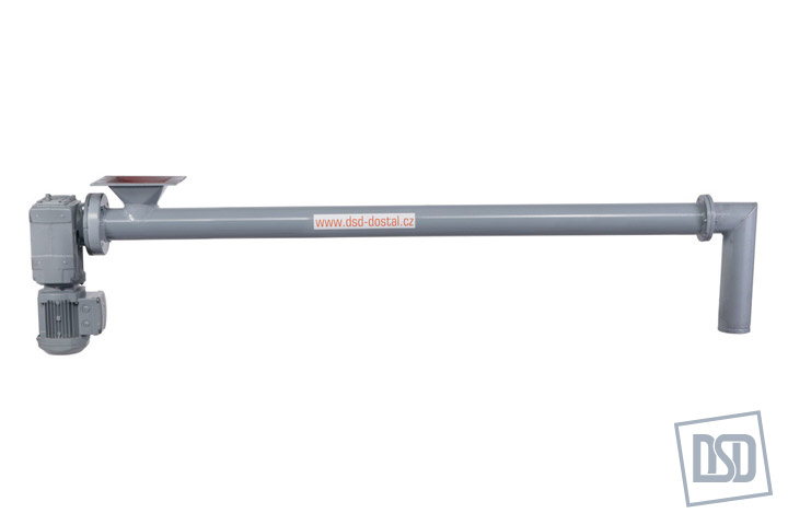
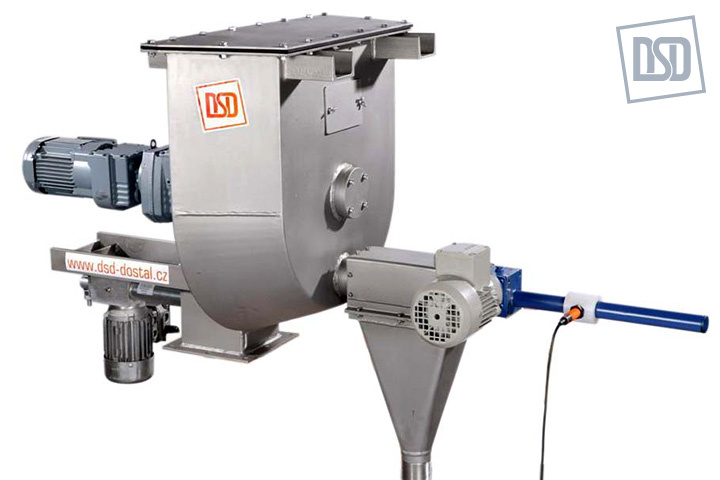
Worm conveyors transport horizontally powdered and fine-grained materials mostly in the building industry. They are used for materials the grain size of which ranges from 0 to 30 mm. The material conveyed must not be sticky, with powdered materials the moisture should not exceed 1% of water, with grained materials 5% of water. When clay portions are present, maximum moisture permitted is 3%. Temperature of the material conveyed ranges from – 30 to 200°C. A number of hoppers and discharging hoppers and their arrangement is designed according to real needs of a customer. The hoppers must not collide with a suspended bearing and on the other hand the discharging hoppers must not interfere with trough joints. Worm conveyors are of dia. 100 – 1000 mm and up to total length of 30 m.Worm conveyors consist of a trough closed with shields with antifriction bearings at ends, special sealing of a worm shaft. The trough is fitted with removable covers, cleaning and inspection holes. The worm shaft is seated in outside bearings. With longer conveyors adjustable suspended bearings are used. Inlet and outlet flanges are supplied either separately and they are welded on at the site or they are welded on already in the workshop. A drive of the worm conveyor is designed as follows: in a standard way it is an electric gearbox connected with the worm shaft by means of a flexible coupling; or chain wheel or socket gearbox.
Worm conveyors are designed according to requirements of a customer based on necessary output, material conveyed and transport distance. Conveyors are supplied completely equipped with a drive, holder of a rotary movement watcher and connecting and anchoring material.
- Mechanical transport - vertical
We guarantee a high level of quality
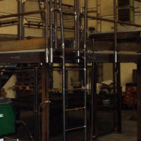
Vertical screw conveyors are designed for vertical transport of powder or granular materials. Transported material should not be adhesive. Temperature of material should be in range -30°C to +200°C. In case of higher material temperature is necessary to discuss with producer. Dosing of material to vertical conveyor should be regulated to avoid overloading of equipment over construction limits. If the material is dosing fitfully, the vertical conveyor must be designed for maximum momental or fitful dosing.Vertical conveyors are not designed for using in explosive atmosphere. Protection against explosive risk needs special design and construction.
Vertical conveyors are not suitable for materials, which causes rust. Conveyors for this type of material needs special construction according to request.
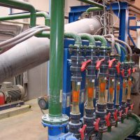
- Fluid transport
We will propose the optimal solution
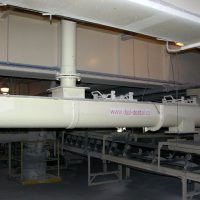
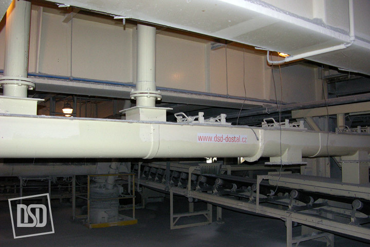
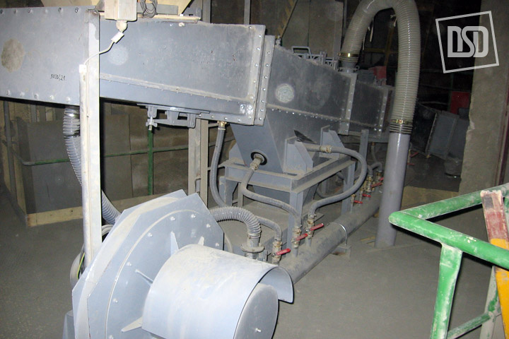
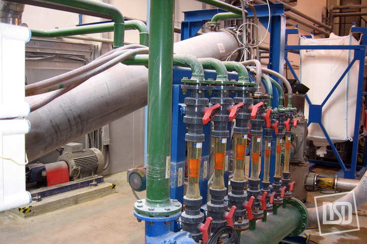
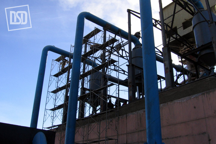
The pneumatic transport is connected to the technological equipment. It transports bulk materials at the distance of up to several hundreds of meters. It consists of few mechanical parts, which is an advantage reducing requirements for maintenance.Air is supplied through fluid slides from high-pressure fans via a cleaning diaphragm made of a special cloth where the material conveyed is aerated (fluidized) and flows in the direction of the slide inclination.
We will prepare a detailed design of the equipment, provide professional implementation and assembly, commissioning of the transport system successfully.
Storage
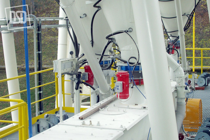
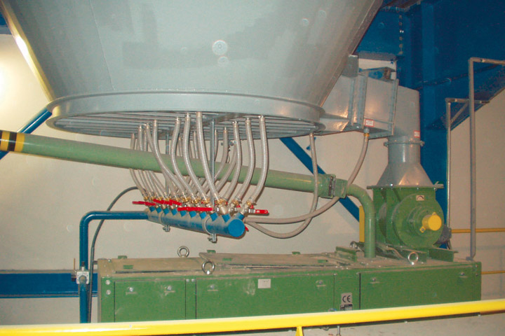
- Aeration equipment
You can easily remove bulk materials
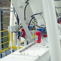
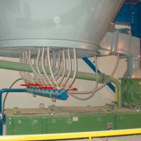
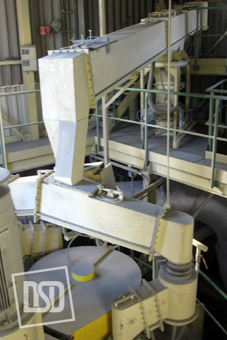
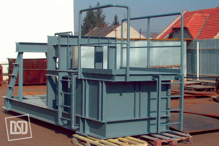
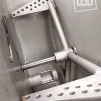
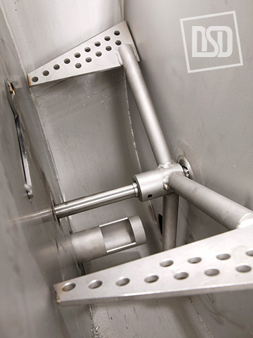
The aeration equipment helps to discharge materials from silos and bins. When bulk materials are stored in silos and bins, material arches are often formed when the material is discharged from the bin bottom. So that the bin would be discharged completely, it is necessary to break arches. Proper aeration prevents formation of arches. If the system is designed correctly, arches are not formed and the material is discharged continuously without troubles. Aeration troughs are used as aeration and transport equipment for powdered, bulk materials.The aeration trough consists of a plate body covered with a stretched cloth permeable by air. Aeration troughs are fixed on the silo or bin bottom inclined in the direction of flow. For the material lying in the trough to be discharged, compressed air is supplied from a source by pipes and hoses to a trough box. Compressed air penetrates evenly through the stretched cloth covering the trough box. Then compressed air goes through the material stored and enriches it with air. This enrichment with air decreases the value of internal friction of the material stored that due to gravitation flows in the inclined trough directly towards the silo discharge. The material and compressed air flow further via a dosing device at the silo discharge onto a conveyor connected.
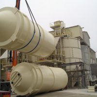
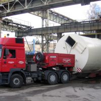
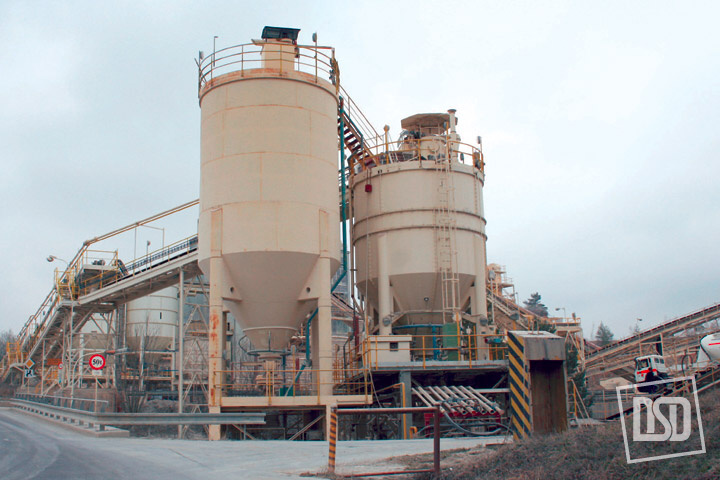
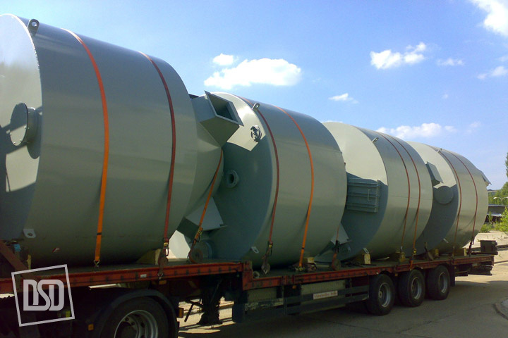
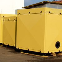
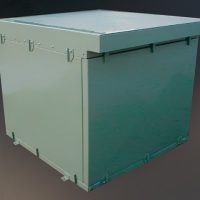
- Bulk material bins
We manufacture, supply and install
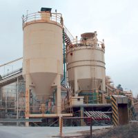
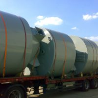
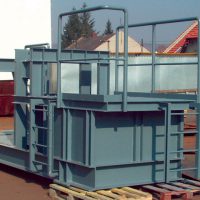
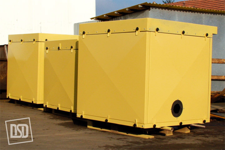
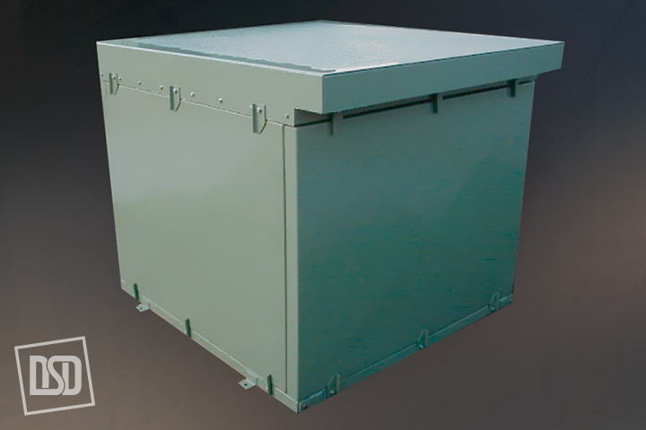
Steel bins are used for the storage of ground material products. The bin is manufactured and supplied complete with anchoring bases, access hole for maintenance staff and flange for a filter to be fixed on the bin top including access to the bin top and safety railings. In case powdered material is stored, bins and silos are equipped with aeration systems i.e. aeration boxes including a source of compressed air, overpressure flaps, filter units etc. The material discharge is either through a central circular hole or one or several lateral outlets. The bin stability is secured with anchoring bases (ring) according to the static calculation. We provide the project documentation of the bin charging, de-dusting and discharge of the stored material to further technological units. We also provide manufacturing documentation of different types of powdered material bins.
Types of steel bins and silos:- circular
- squared
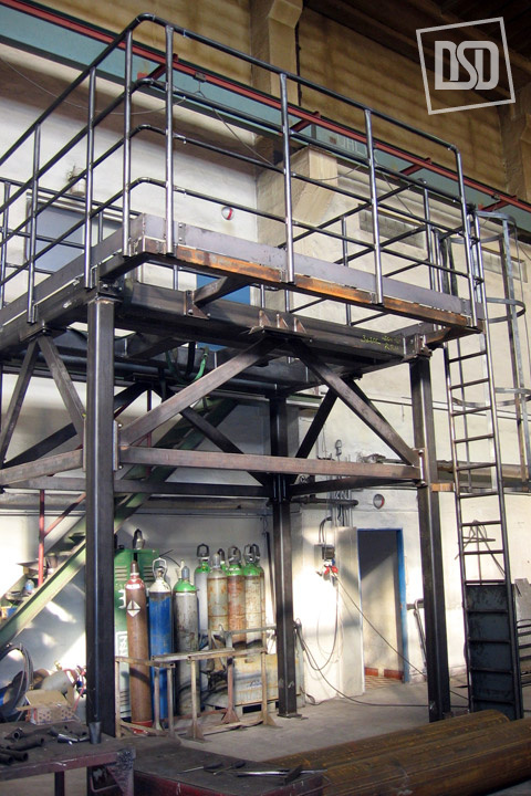
- including supporting structures
Design:
- welded
- screwed
Surface finish:
- outside, if a customer requires
- inside, according to the material stored
- antistatic coats
- wear-resistant coats
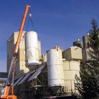
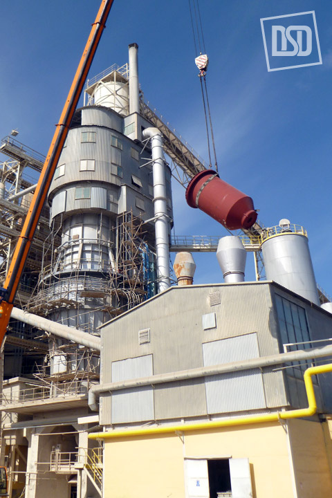
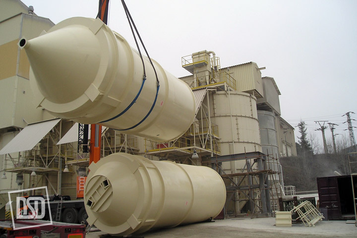
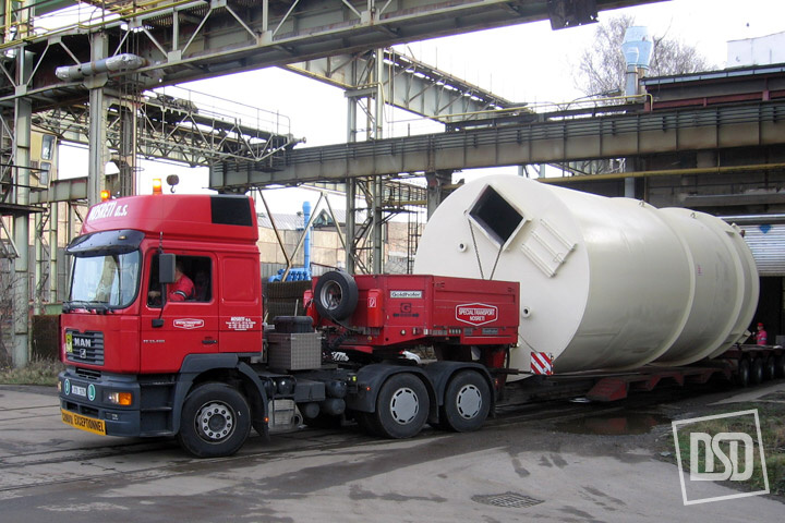
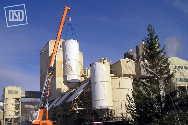
- Silos
We manufacture, supply and install
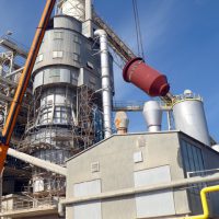
Cooling
- Vertical cooler
Long-term maintenance-free operation
Minimum vibrations and noise
Easy to set up and adjust
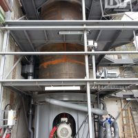
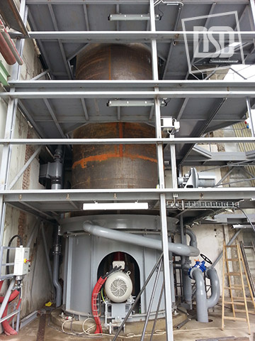
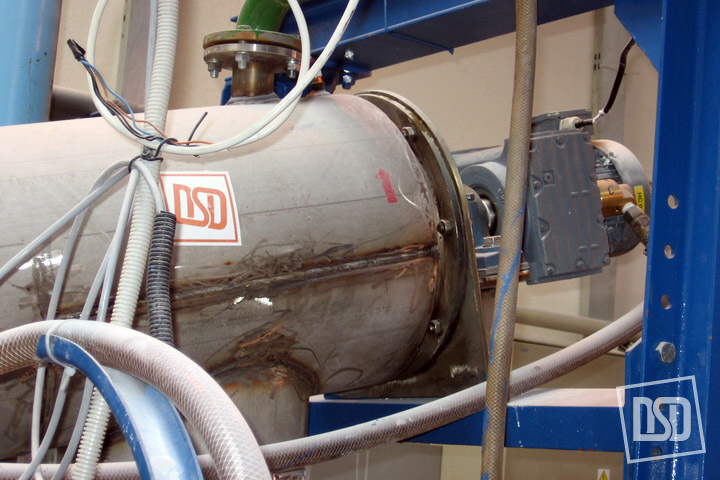
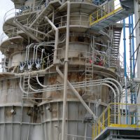
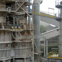
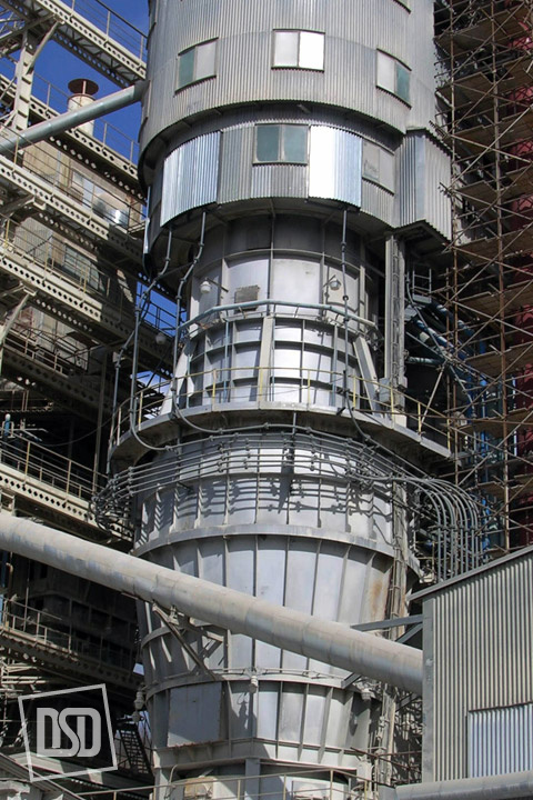
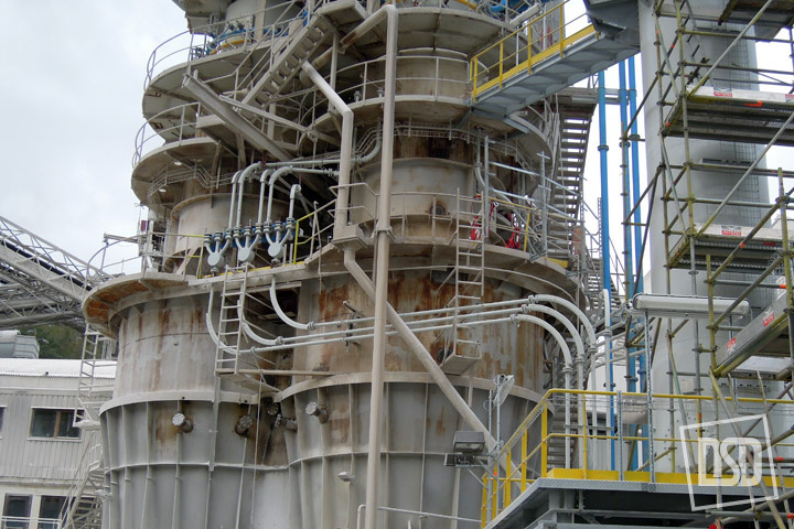
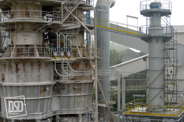
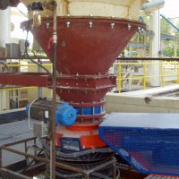
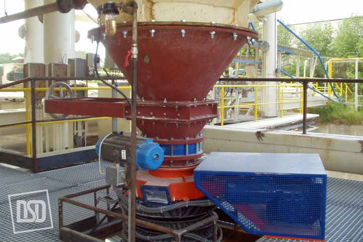
DSD powdered material vertical cooler is constructed on a principle of indirect cooling i.e. that cooling medium, in this case water, does not come into contact with cooled material. With this way of cooling as against direct water injection to hot ground material, the final product quality is not affected. Although the cooler can be used for reduction of temperature of different fine-ground materials, it is used mostly for ground cement cooling.
Reasons why to cool cement:
- At temperatures 80 – 90°C gypsum breaks down according to the formula CaSO4 . 2 H2O = CaSO4 . . H2O + 1 . H2O while plaster forms. Liberated water vapor condensates and reacts with clinker minerals. Aggregates, clusters and deposits occur and sometimes even arches are formed in a silo.
- After hexavalent chromium in cement is reduced with ferrous sulfate heptahydrate (FeSO4 . 7 H2O), which is broken down at temperature 64°C, 6 molecules of water are separated and so the sulfate is dissolved. Therefore sulfate should be added to cement of temperature lower than 60°C.
- Paper bags get torn when temperature of packed material is more than 80°C. Optimum temperature is less than 65°C. Capacity of the biggest DSD vertical cooler is 140 t/h. Cooling water consumption ranges from 0,6 to 0,8 m3/1 t of cement according to ground cement temperature.
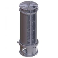
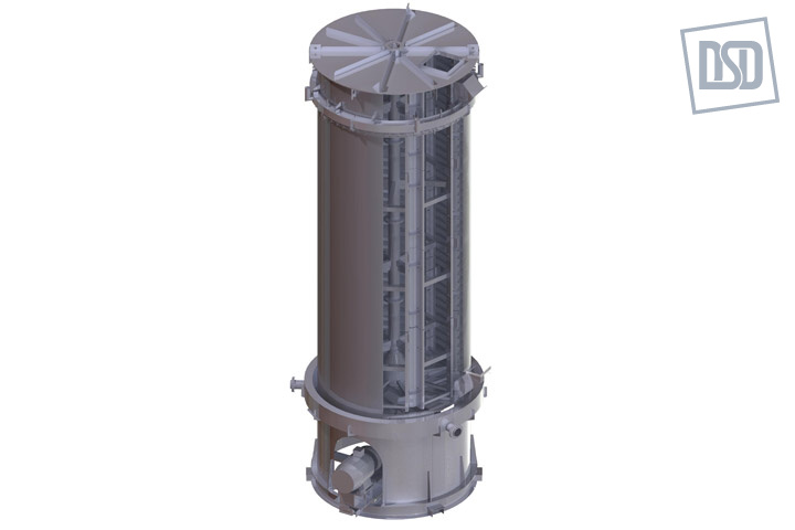
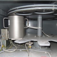
COOLER DESIGN
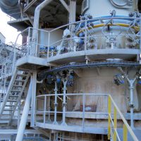
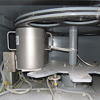
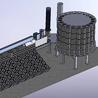
The cooler consists of a vertical cylindrical vessel in the inside of which there is a peripheral worm conveyor of material. The bottom is fitted with aerating plates, manhole and cleaning hole. Cooled material is supplied to the lower part of the cooling cylinder on its bottom where it is aerated and then by means of wipers positioned on a supporting basket of the worm, it is pushed on the peripheral wall of the cooler and then lifted up by worm blades and with its centrifugal force it is lifted along the cooled wall of the cylindrical vessel to the discharge positioned in the upper part. So this is the optimum heat exchange between material, cooled wall and cooling water. Water supplied to the upper part through the cooler lid is taken to a peripheral distributing channel out of which water flows evenly on the outer side of the casing. Brushes positioned here provide even water distribution on the outer wall of the vessel. Warm water flowing down freely is colleted in a collecting channel and it is returned back for further use through a discharge tube, it is either cooled again to temperature required and returned to the material cooling system or it is used as utility warm water. The water system is perfectly separated from the powder system and so water cannot penetrate into cooled material.
The cooler vessel is equipped with outside, self-supporting, plastic casing into which the system of air nozzles is fitted tangentially and these should increase velocity of air flow along the cooler wall and so support water evaporation from the cooler wall. This effect helps significantly to increase the cooler capacity. Vapor saturated with water is taken by a piping to the discharging stack and so the cooler environment is not covered in frost much in winter period. Aerating plates on the bottom and air nozzles are supplied with pressure air from a fan which is part of the cooler equipment.
The worm conveyor consists of several exchangeable parts that can be easily adjusted to the appropriate minimum gap between the conveyor and outside casing. With the gap size the period of material stay in the cooler is adjusted and so its efficiency. The worm cooler is driven by an angle gearbox in horizontal position placed under the cooler bottom incl. motor. For the maintenance to be easy the drive is well accessible and it can be dismantled by means of a lifting mechanism.
When the cooler is broken down, rest of material can be discharged through the cleaning hole and discharging chute by means of an auxiliary drive. The cooled material leaves the cooler through the upper discharging chute to a pneumatic conveying through or other conveying system.
As in cooling the side sprayed with water is covered with water algae, an independent cleaning circuit, used to remove these impurities from the cooler wall, is positioned in the water circuit. This cleaning circuit is designed so that cleaning lye would not get in cooling water.
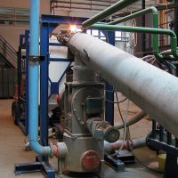
- Screw double-walled cooler
Complete cooling without worries
- dlouhodobý provoz bez údržby
- minimální vibrace a hluk
- žádná nutnost seřizování
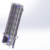
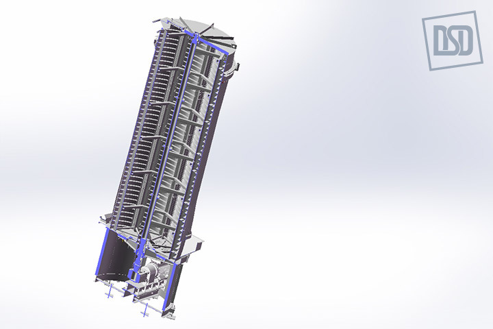
Šnekové chladiče jsou určeny pro snížení teploty práškového materiálu.
Chlazení probíhá ve dvou stupních chladiče. První stupeň je tvořen dvojitou šnekovnicí, uloženou ve dvou trubkách, umístěných těsně vedle sebe. Teplo chlazeného materiálu je odváděno vodou, která protéká dvojitými stěnami trubek a víka a též dutými hřídeli šnekovnice. Vysoké intenzity chlazení je dosaženo promícháváním chlazeného materiálu lopatkami, přivařenými ke šnekovnici, které s malou vůlí prochází nad dnem koryta. Chlazený materiál postupuje do druhého stupně chladiče, který je tvořen trubkovým šnekem, který se skládá z trubky a šnekovnice. Trubka má dvojitou stěnu, kterou protéká chladicí voda, která rovněž protéká dutou hřídelí.
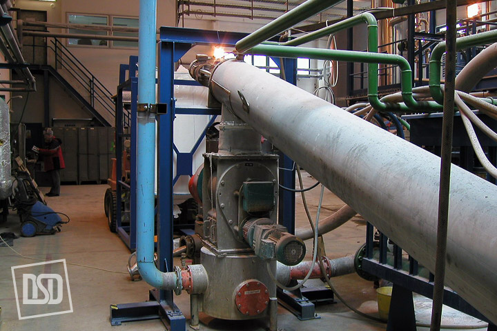
Výpad materiálu mezi prvním a druhým stupněm chladiče a na výstupu z druhého stupně do turniketu pneumatické dopravy je uskutečněn přechodovým kuželem, který je zvenčí překryt skelnou tkaninou.
Ke žlabu a trubce jsou přivařeny příruby s odnímatelnými čely. Šnekovnice jsou uloženy ve valivých ložiscích, která jsou uložena v samostatných nebo přírubových domcích.První stupeň šnekového chladiče pohání dvě nástrčné převodovky s elektromotory firmy SEW. Pracovní otáčky obou elektromotorů se nastavují během zkušebního provozu chladiče, případně lze otáčky regulovat podle momentálního výkonu rotační pece.
Chladící vodu pro hřídele šnekovnic přivádí i odvádí rotační přivaděče našroubované na konce hřídelí. To umožňuje Long-term maintenance-free operation. Aby se však hřídele nepoškodily, musí být při otáčení vždy naplněny vodou. Díly chladiče jsou vyrobeny z materiálu 17 251, díly chlazené vodou pak z materiálu 17 240. Oba stupně chladiče jsou uloženy na podpěrných ocelových konstrukcích, které umožňují v malém rozsahu měnit sklon šnekových chladičů a tím změnit rychlost postupu materiálu i intenzitu chlazení.
Potřeba změny sklonu obou stupňů chladiče se ověřuje během zkušebního provozu.Konstrukční řešení snižuje na minimum vibrace a hluk chladicího zařízení. To je kotveno na ocelovou nosnou konstrukci podpěrnými patkami. Právě nosná konstrukce umožňuje v malém rozsahu měnit sklon chladičů posunutím podpěr. Nosná konstrukce se upevňuje pomocí kotevních šroubů v betonové podlaze. Chladič je konstrukčně proveden bez nutnosti seřizování, pracuje v rozsahu nastavených výrobních parametrů. Provozní otáčky lze měnit frekvenčními měniči elektromotorů podle provozních zkušeností a výkonu rotační pece, v níž je produkt ochlazován.
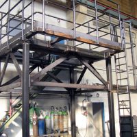
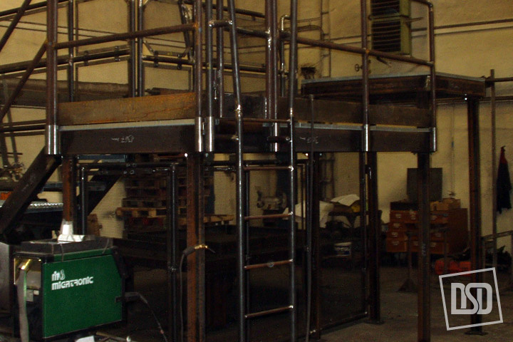
Non Standard Production
- Steel constructions
Realization of non-standard orders is our standard
- Atypické konstrukce a rozměry
- Specifikace na přání zákazníka
- Projektová a výrobní dokumentace
- Dlouhá tradice
- Spolehlivý a kvalitní tým odborníků
Vedle standardních typů a velikostí je možné vyrobit ocelové konstrukce, ventilátory a výrobky atypických rozměrů. Projekce a výroba se přizpůsobuje specifickým požadavkům zákazníka. Stejná možnost přizpůsobení požadavkům zákazníka existuje i u pneumatické dopravy, šnekových dopravníků a všech ostatních výrobků. Samozřejmostí je zpracování projektové a výrobní dokumentace podle specifikací klienta.
- Atypické konstrukce a rozměry
- Untypical machinery and equipment
Realization of non-standard orders is our standard
- Atypické konstrukce a rozměry
- Specifikace na přání zákazníka
- Projektová a výrobní dokumentace
- Dlouhá tradice
- Spolehlivý a kvalitní tým odborníků
Vedle standardních typů a velikostí je možné vyrobit ocelové konstrukce, ventilátory a výrobky atypických rozměrů. Projekce a výroba se přizpůsobuje specifickým požadavkům zákazníka. Stejná možnost přizpůsobení požadavkům zákazníka existuje i u pneumatické dopravy, šnekových dopravníků a všech ostatních výrobků. Samozřejmostí je zpracování projektové a výrobní dokumentace podle specifikací klienta.
- Atypické konstrukce a rozměry
- Noise protection covers
Realization of non-standard orders is our standard
- Atypické konstrukce a rozměry

- Specifikace na přání zákazníka
- Projektová a výrobní dokumentace
- Dlouhá tradice
- Spolehlivý a kvalitní tým odborníků
Vedle standardních typů a velikostí je možné vyrobit ocelové konstrukce, ventilátory a výrobky atypických rozměrů. Projekce a výroba se přizpůsobuje specifickým požadavkům zákazníka. Stejná možnost přizpůsobení požadavkům zákazníka existuje i u pneumatické dopravy, šnekových dopravníků a všech ostatních výrobků. Samozřejmostí je zpracování projektové a výrobní dokumentace podle specifikací klienta.
- Atypické konstrukce a rozměry
- Technological units
Realization of non-standard orders is our standard
- Atypické konstrukce a rozměry
- Specifikace na přání zákazníka
- Projektová a výrobní dokumentace
- Dlouhá tradice
- Spolehlivý a kvalitní tým odborníků
Vedle standardních typů a velikostí je možné vyrobit ocelové konstrukce, ventilátory a výrobky atypických rozměrů. Projekce a výroba se přizpůsobuje specifickým požadavkům zákazníka. Stejná možnost přizpůsobení požadavkům zákazníka existuje i u pneumatické dopravy, šnekových dopravníků a všech ostatních výrobků. Samozřejmostí je zpracování projektové a výrobní dokumentace podle specifikací klienta.
- Atypické konstrukce a rozměry
- Ventilators HP
Realization of non-standard orders is our standard
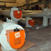
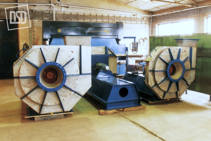
There are atypical high-pressure fans of pressure up to 8 kPa and circulating wheel dia. up to 1 000 mm. A radial fan is driven with electric motors of different power outputs. The circulating wheel is fixed directly on an electric motor shaft, the spiral box and stool are welded of plate. The fan inlet is adapted for an air filter to be fixed. The fan is anchored either directly or flexibly through insulators on an anchoring frame welded of profiled material. The fan can be positioned in a plate cover equipped with an anti-noise insulation. Left or right design or outlets are according to requirements of a customer.
Fans are used as a pressure air source for air slides. Fans cannot be used for the transport of explosive air mix of corrosion character containing fiber dust and admixtures that could cause clogging.Fans can be positioned both outside and also inside where the ambient temperature ranges from -20°C to +40°C. A producer will determine the fan type and motor size on the basis of air-technical parameters required.
Noise level of the fan positioned in the anti-noise cover does not exceed 65 dB (measured in accordance with ČSN ISO 3744).
The Czech commercial inspection verified the declaration of conformity in 06/2001.
FAN FLOW RATE
[m3/s]PRESSURE
[kPa]MOTOR
[kW]HP01-50/695 0,75 8 11 HP04-75/630 0,23 8 5,5 HP05/650 0,4 8 7,5 HP04-90/560 0,47 6,8 7,5 HP05-60/545 0,07 6,3 3 HP05/595 0,33 6,3 5,5 HP04X/525 0,41 5,9 5,5 HP05/550 0,2 6,2 4 HP05/565 0,25 6,2 4 HP05-65/570 0,14 6,5 3 - Transport piping
Realization of non-standard orders is our standard
- Atypické konstrukce a rozměry
- Specifikace na přání zákazníka
- Projektová a výrobní dokumentace
- Dlouhá tradice
- Spolehlivý a kvalitní tým odborníků
Vedle standardních typů a velikostí je možné vyrobit ocelové konstrukce, ventilátory a výrobky atypických rozměrů. Projekce a výroba se přizpůsobuje specifickým požadavkům zákazníka. Stejná možnost přizpůsobení požadavkům zákazníka existuje i u pneumatické dopravy, šnekových dopravníků a všech ostatních výrobků. Samozřejmostí je zpracování projektové a výrobní dokumentace podle specifikací klienta.
- Atypické konstrukce a rozměry
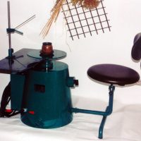
Automation of sampling
- General information
At present sampling is an integral part of technological control of modern industrial treatment branches such as industry of building materials, chemical industry and mining of ores, minerals and fuels.
To control quality of bulk material, it is necessary to take a representative sample during production and test it in a laboratory or keep it as a proof of quality. For this purpose DSD – Dostál, a. s. developed different types of sampling devices incl. the following treatment of samples.
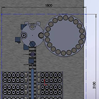
Sampling stations of DSD – Dostál, a. s. represent a set of machines providing taking of partial samples, modification of grain size, distribution of material flow, homogenizing, transport of waste portion and keeping of final samples.
There are sampling elements such as screw, piston, fluid-slide, bucket and hammer samplers.
Grain size of the sample is modified in a hammer crusher lined against sticking or abrasion. Outlet grain size is (0 – 10) mm.
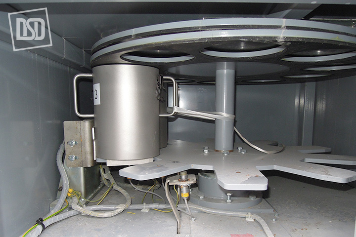
Material flow is distributed by continuous disc or tube dividers that allow reduction of the material flow in the ratio from 4:1 up to 40:1.Partial samples are homogenized in a homogenizer of effective volume 20 dm3. Preparation of the time-average sample is a very important item of the whole sampling station.
The final sample representing a requested outlet of the sampling station is dosed out of the homogenizer to the collecting pot or to the system of collecting pots positioned in a carousel.
Sampling stations can be connected to the system of tubular post providing transport of the final sample from the sampling place to testing e.g. laboratory.
Samples can be taken:
- from chutes
- from transport fluid-slides
- from belt conveyors
It is possible to select a system of the sampling station control (ALLEN BRADLEYTM, SIEMENSTM).
Types of sampling stations according to grain size distribution and way of evaluation:
1. for spot samples
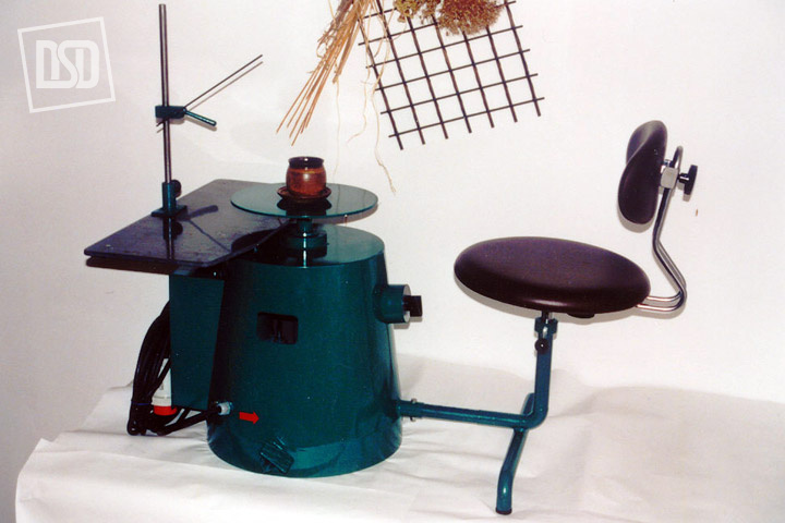
- VSR/screw sampling station, hand-operated (grain size 0 – 3 mm)
- SSM/screw sampling station, automatic (grain size 0 – 3 mm)
- FSM/fluid-slide sampling station, automatic (grain size 0 – 1 mm)
- LO/bucket sampling station, automatic (grain size 0 – 40 mm)
- KLT/hammer sampling station, automatic (grain size 0 – 10 mm)
- PVZ/piston sampling station, automatic (grain size 0 – 3 mm)
2. for sectional samples
- ASS/screw sampling station with a homogenizer and piston sampler
- AFS/fluid-slide sampling station with a homogenizer and piston sampler
- ALOS/bucket sampling station with a crusher, divider, homogenizer and piston sampler
- KDDS/hammer sampling station with a crusher and divider
Sets of sampling stations can be combined according to particular requirements for sampling.
Equipment of sampling stations can be adapted to requirements of sampled material with an increased temperature (up to 350°C) or to areas requiring the ATEX certification.
- Description
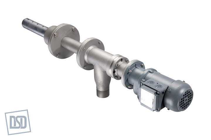
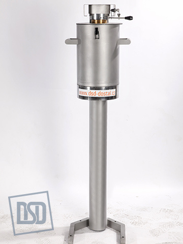
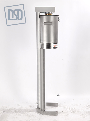
SCREW SAMPLING STATION
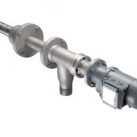
The equipment is used for automatic sampling of materials from chutes, hoppers, discharging heads of pneumatic fluid-slides and similar spaces, in which the material is transported with the help of free fall. The equipment is suitable for dry, bulk, non-sticking powder or fine-grained materials (of max. grain size 3 mm).
The admissible material temperature for the type SSM 01 – 120 is up to 120°C. If required, the equipment even for higher temperatures can be manufactured.
The sampling station consists of the sampler with a motor drive, ball valve with a motor drive, chute with a vibration motor, box of the sampling station including a pot for samples and control unit in the switchboard.
The sampler is designed as an overhung screw conveyer with an open inlet. The screw is made of stainless steel with thermal resistance up to 120°C. The extraction part, which is positioned in the direction of material flow, is modified according to the properties and grain size of the sampled material and its surface is lined with hard chrome. The sampling unit is attached to the equipment on the carrying neck with a flange. If needed, this sampling unit can be removed and the neck can be blinded with a blind flange. The equipment is driven by a motor.FLUID-SLIDE SAMPLING STATIONÁ
The equipment is used for automatic sampling of materials from pneumatic fluid-slides and can be used for all materials suitable for transportation by fluid-slides.
The admissible material temperature for the type FSM 01 – 120 is up to 120°C. If required, the equipment even for higher temperatures can be manufactured.HOMOGENIZATION OF SAMPLES
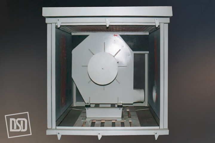
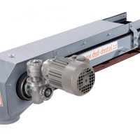
The sample homogenizer can be incorporated into the chute if required by the production technology. It homogenizes particular samples. The samples fall through the chute into the homogenizer pot, where they are agitated by blades of the mixing equipment controlled by an electric gearbox with the horizontal axis of rotation. The homogenizer is designed for working capacity of 20 dm3 and maximum capacity of 35 dm3.ELECTRIC SWITCHBOARD for screw and fluid-slide sampling stations
Electric switchboards are delivered in two variants. The first variant controls simple assemblies of sampling stations without a homogenizer. This control unit is based on the control automat Allen Bradley PICOTM or Siemens LOGO.
Sampling controlled by this control unit is performed automatically without an operator either by one single sampling or multiple sampling with idle periods. The number of samples and idle periods are set on the control unit. This unit can be adjusted only locally, however, signals about the condition of sampling including error messages can be transmitted to the central control system (control room). The control centre can interrupt the cycles of sampling in the system and start them and continue operation again. The other variant of the electric switchboard is designed for more complex assemblies of sampling stations with a homogenizer. This control unit is based on the control automat Allen Bradley FLEX LOGIX or Siemens SIMATIC S7-315 2DP. To provide communication with the superior control system of operation, the interface ETHERNET or PROFIBUS is used.SAMPLING STATION WITH A HAMMER SAMPLER
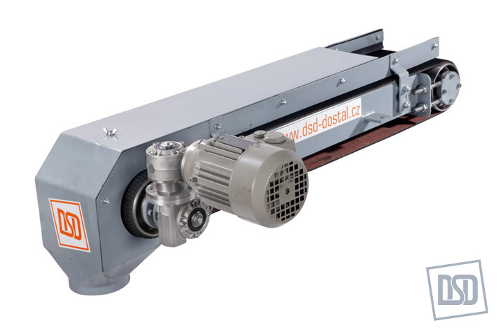
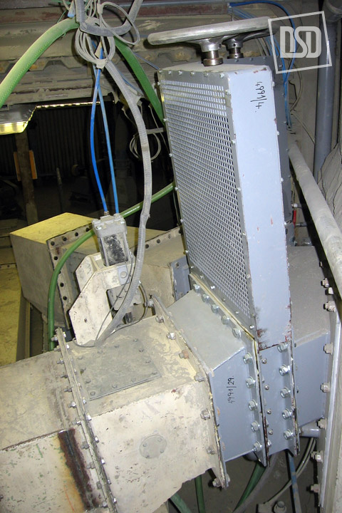
The equipment is used for automatic sampling of materials from a conveyor belt in standard conditions under operating temperatures above 0°C. The equipment is suitable for dry, bulk, non-sticking grained materials (maximum grain size 150 mm). The whole process of sampling and the consequent processing of the sample are controlled by the control automat with a possible check and interruption of the sampling process by a superior system.SAMPLING STATION WITH A BUCKET SAMPLER
The equipment is used for automatic sampling of material from a chute or transfer tower of the conveyor belt in normal conditions under operating temperatures above 0°C. The equipment is suitable for dry, bulk, non-sticking grained materials (maximum grain size 40 mm, max. 60 mm). The whole process of sampling and the consequent processing of the sample are controlled by the control automat with a possible check and interruption of the sampling process by a superior system.SAMPLING STATION OF HOT RAW MEAL
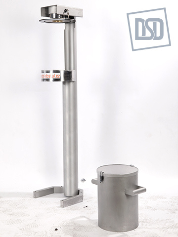
The sampling station of hot raw meal is a single-purpose machine and it is used for the automatic taking of samples of hot fine ground powdered material to the maximum grain size of 1 mm. The sampler is not designed for areas where there is a danger of explosion. Maximum permissible temperature of environment of material sampled is 1000°C.
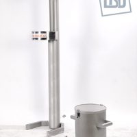
The sampling station capacity is sized for taking 4 – 6 partial samples in the course of 1 hour that are continuously homogenized and cooled and the final sample of approx. 300 g is ready to be taken in a portable vessel for the sample.SLUDGE SAMPLING STATION
The equipment is used for automatic sampling of raw sludge on the basis of ground raw material components – fine slurry with approx. 36 % of water.
Sludge temperature – standard from 0°C to max. 35°C The sludge sampled must be of a primary fineness like sludge dosed to the kiln. - Sampling elements
Automatic sample analysis for your review
- Pro prostory s volným pádem materiálu
- Maximální velikost zrna 3mm
- Až pro teploty materiálu 350°C
- Automatický odběr bez obsluhy
- Na přání homogenizátor vzorků
Vzorkovací stanice je určena k odběru vzorků z prostorů, ve kterých se materiál pohybuje volným pádem, a kde přetlak nebo podtlak proti okolí nepřekračuje 10 kPa (skluzová potrubí, násypky, výpadové hlavy pneumatických dopravních žlabů). Používá se pro suché, sypké, nelepivé práškové nebo jemně granulované materiály (do maximální velikosti zrna 3 mm). Přípustná teplota materiálu je pro standardní provedení do 90°C, na přání je možno vyrobit zařízení i pro teploty vyšší (350°C). Odběr vzorku je prováděn u automatového provedení automaticky bez zásahu obsluhy a to buď jedním samostatným odběrem nebo jako vícenásobný odběr vzorků s časovými prodlevami. Dle požadavků zákazníka se do vzorkovací stanice řadí homogenizátor vzorků, sloužící k homogenizaci odebraných dílčích vzorků.
- Pro prostory s volným pádem materiálu
- Sample treatment
Automatic sample analysis for your review
- Pro prostory s volným pádem materiálu
- Maximální velikost zrna 3mm
- Až pro teploty materiálu 350°C
- Automatický odběr bez obsluhy
- Na přání homogenizátor vzorků
Vzorkovací stanice je určena k odběru vzorků z prostorů, ve kterých se materiál pohybuje volným pádem, a kde přetlak nebo podtlak proti okolí nepřekračuje 10 kPa (skluzová potrubí, násypky, výpadové hlavy pneumatických dopravních žlabů). Používá se pro suché, sypké, nelepivé práškové nebo jemně granulované materiály (do maximální velikosti zrna 3 mm). Přípustná teplota materiálu je pro standardní provedení do 90°C, na přání je možno vyrobit zařízení i pro teploty vyšší (350°C). Odběr vzorku je prováděn u automatového provedení automaticky bez zásahu obsluhy a to buď jedním samostatným odběrem nebo jako vícenásobný odběr vzorků s časovými prodlevami. Dle požadavků zákazníka se do vzorkovací stanice řadí homogenizátor vzorků, sloužící k homogenizaci odebraných dílčích vzorků.
- Pro prostory s volným pádem materiálu
- Placing
Automatic sample analysis for your review
- Pro prostory s volným pádem materiálu
- Maximální velikost zrna 3mm
- Až pro teploty materiálu 350°C
- Automatický odběr bez obsluhy
- Na přání homogenizátor vzorků
Vzorkovací stanice je určena k odběru vzorků z prostorů, ve kterých se materiál pohybuje volným pádem, a kde přetlak nebo podtlak proti okolí nepřekračuje 10 kPa (skluzová potrubí, násypky, výpadové hlavy pneumatických dopravních žlabů). Používá se pro suché, sypké, nelepivé práškové nebo jemně granulované materiály (do maximální velikosti zrna 3 mm). Přípustná teplota materiálu je pro standardní provedení do 90°C, na přání je možno vyrobit zařízení i pro teploty vyšší (350°C). Odběr vzorku je prováděn u automatového provedení automaticky bez zásahu obsluhy a to buď jedním samostatným odběrem nebo jako vícenásobný odběr vzorků s časovými prodlevami. Dle požadavků zákazníka se do vzorkovací stanice řadí homogenizátor vzorků, sloužící k homogenizaci odebraných dílčích vzorků.
- Pro prostory s volným pádem materiálu
- Storage
Automatic sample analysis for your review
- Pro prostory s volným pádem materiálu
- Maximální velikost zrna 3mm
- Až pro teploty materiálu 350°C
- Automatický odběr bez obsluhy
- Na přání homogenizátor vzorků
Vzorkovací stanice je určena k odběru vzorků z prostorů, ve kterých se materiál pohybuje volným pádem, a kde přetlak nebo podtlak proti okolí nepřekračuje 10 kPa (skluzová potrubí, násypky, výpadové hlavy pneumatických dopravních žlabů). Používá se pro suché, sypké, nelepivé práškové nebo jemně granulované materiály (do maximální velikosti zrna 3 mm). Přípustná teplota materiálu je pro standardní provedení do 90°C, na přání je možno vyrobit zařízení i pro teploty vyšší (350°C). Odběr vzorku je prováděn u automatového provedení automaticky bez zásahu obsluhy a to buď jedním samostatným odběrem nebo jako vícenásobný odběr vzorků s časovými prodlevami. Dle požadavků zákazníka se do vzorkovací stanice řadí homogenizátor vzorků, sloužící k homogenizaci odebraných dílčích vzorků.
- Pro prostory s volným pádem materiálu
Regulation
- Tourniguets
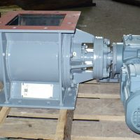
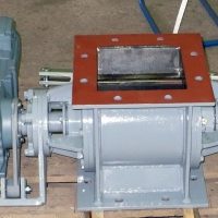
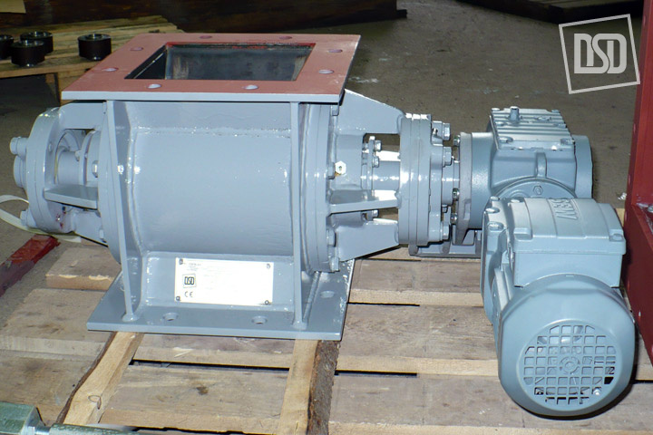
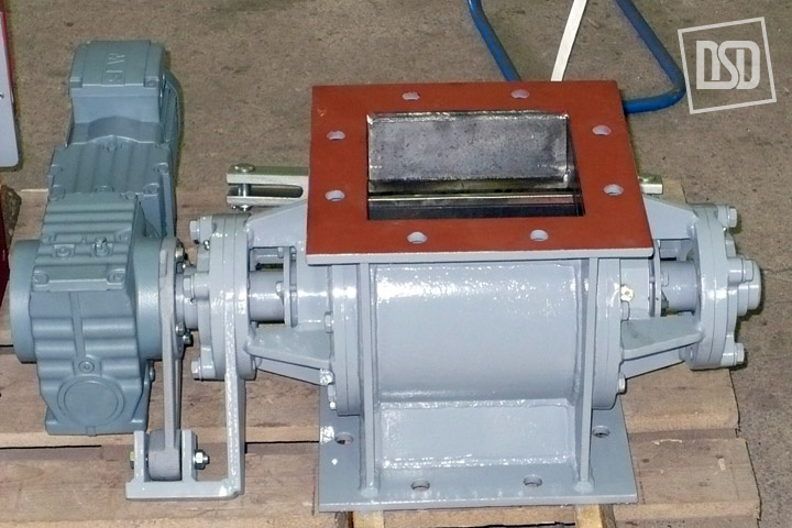
 Rotační turniketový podavač (dále jen RTP) sestává z lopatkového hřídele poháněné elektromotorem a uloženém v prachotěsném svařovaném tělese. Lopatky hřídele jsou opatřeny lamelami. Těleso je na vstupu a výstupu opatřeno připojovací přírubou. Používá se pro stejnosměrné podávání a dávkování suchých, nelepivých a sypkých hmot o zrnitosti menší než 3 mm. RTP není určen pro použití v potencionálně výbušném prostředí.
Hlučnost zařízení nepřesahuje hlučnost pohonu.
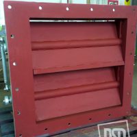
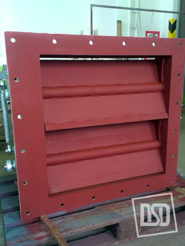
- Regulating flaps
- Cut off gates
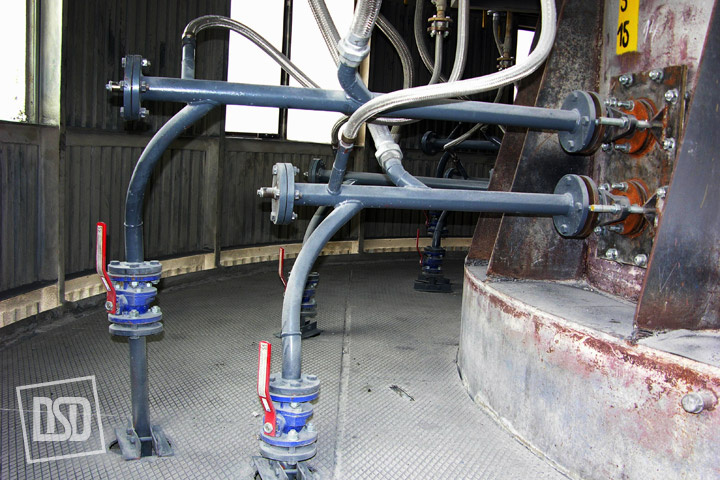
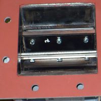
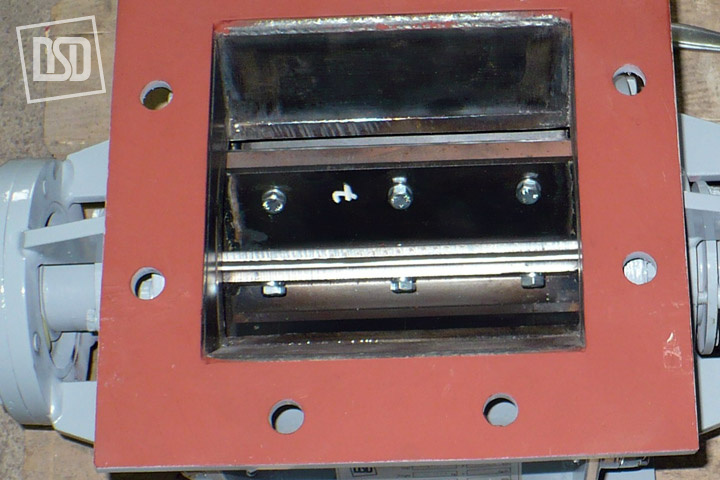
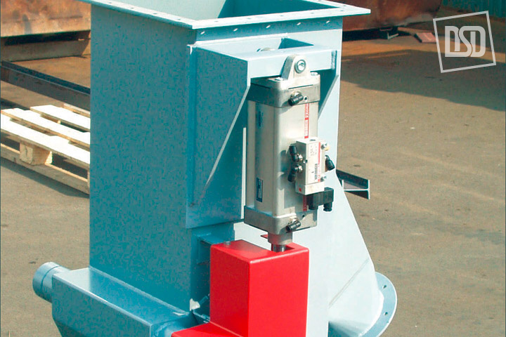
 The cut-off gate is used to stop or throttle the operating medium flow. The closing plate is set in motion by turning the hand wheel, chain wheel, by the el. motor via the gearbox or pneumatic cylinder. It is closed by turning the screw clockwise, with pneumatic cylinders by the forward motion.
The cut-off gate is used as a closing or throttling device for dry, non-sticking, powdered or grained materials (e.g. raw meal, all kinds of cement, flue ash from electrostatic precipitators, ground limestone, bauxite, metallic agglomeration powders, pulverized ores etc.)
Dust-tightness between areas to be divided is not guaranteed.
Maximum operation temperature up to 120°C – standard design.
Maximum operation temperature up to 250°C – stainless design.
Designs with a pneumatic drive or electric motor – with a rustless closing board.
The noisiness of the equipment does not exceed the drive noisiness.
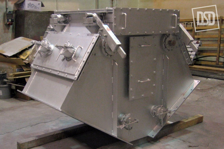
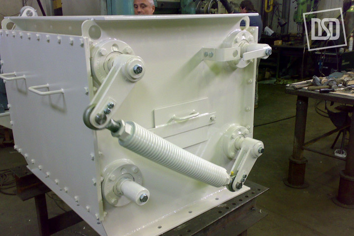
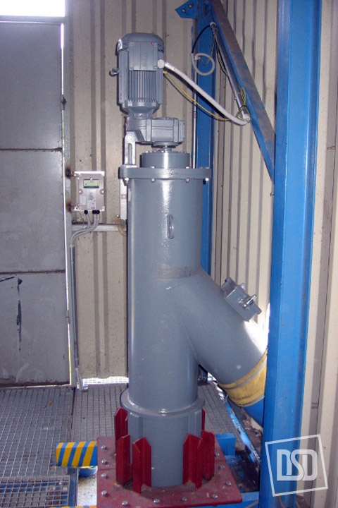
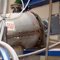
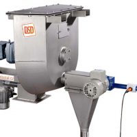
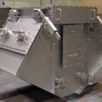
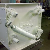
Coarse particle separator
In the right place, at the right time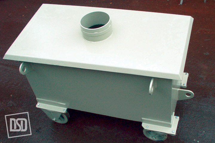
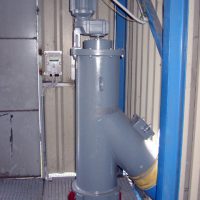
The coarse particle separator is an integral part of the pneumatic fluid transport. It is arranged in a transport line where coarse particles, metal pieces and similar undesirable clusters must be separated from the material conveyed. Especially where the connected technological equipment could be damaged. E.g. before inlets to dynamic separators, packaging machines etc. Particles collected are regularly discharged from the separator by a revolving gate or a pair of synchronized pneumatically controlled slide valves at the separator outlet.
The mix separated is further divided in a cleaning box into material that is returned to the circuit and coarse portion collected in a metal container.
